Picking up where we left-off in the previous post in this series, where we had a look at the physical materials (the wood, fasteners, rods, bolts, nuts, screws, and sundry); in this post we will look at the vision as-a-whole.
No more shrouds of mystery, if you have been unable to "see" the tool until now, this is the post that I expect to bring that vision to light. Until now I have held back the overhead models and profile view. Until now the most anyone has seen are side views, but in this post You will see up-close every angle (or as I refer to it, 6-up orientation modeling which involves modeling every part from each side of 3 axes).
Let's go through the fully-baked mock-ups, accurate to one ten-thousandth of an inch with clearances, tolerances, run-out, and idiocy accounted for (I can make a surprising number of mistakes on this thing and still end up with a fully functional tool, as I prepared for all conceivable mistakes [... that I could make]).
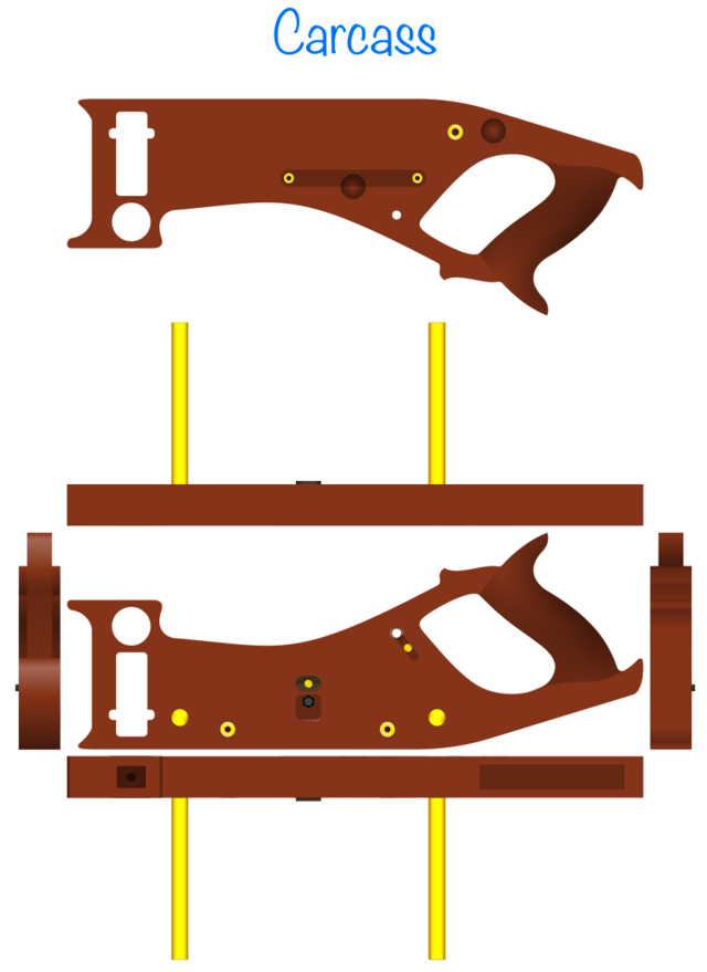
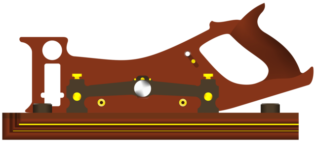
First, let's build up a mental image of the carcass. Here is the 6-up orientation of the carcass. Every bit of hardware shown is epoxied permanently into the wood. So for example, the unthreaded 1/2" diameter brass rod jutting out perpendicular from the plane is epoxied into the wood permanently, as-are the threaded inserts, magnets, Ebony standoff, and 1/4-20 swivel nut.
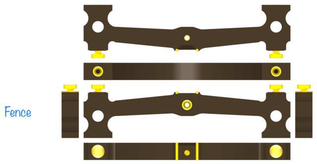
Now, before we go slapping a blade on it (which goes on the right side of the plane) let's look at the fence system (which goes on the left side of the plane, where the brass rod sticks out):
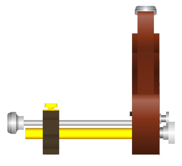
Now, if we slip that fence onto the brass rods, drive a 1/4-20 threaded rod through the threaded insert in the center of the fence, use thread-locker to lock one end of the threaded rod to the swivel nut in the carcass, and finally use thread locker to attach a domed knurled knob to said threaded-rod, this is what it looks like from above:
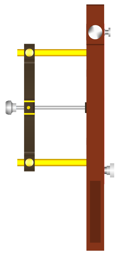
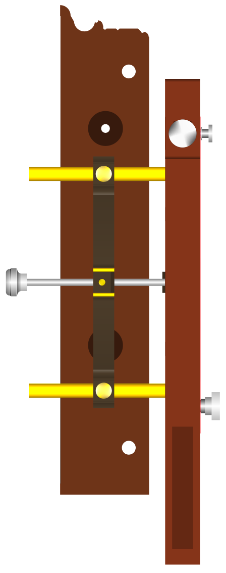
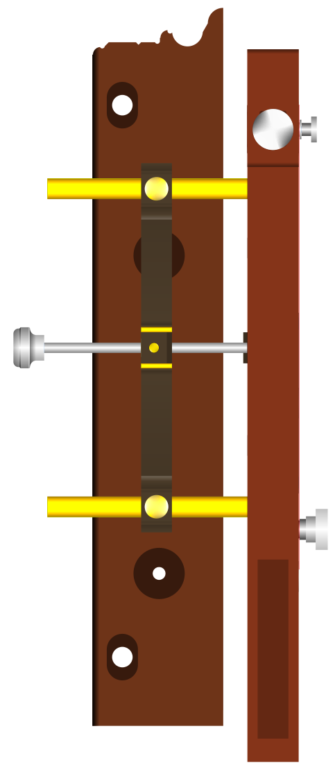
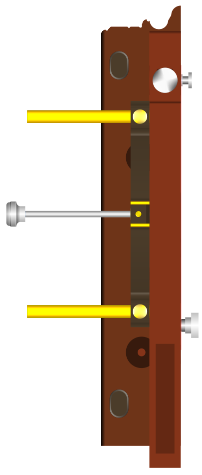
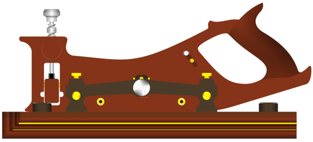
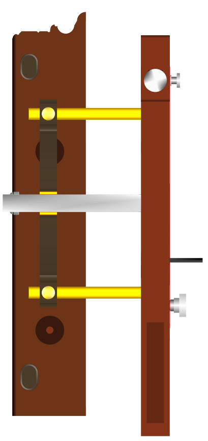
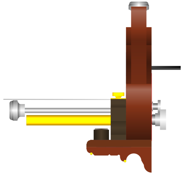
Here is what that looks like looking at the back of the plane (from the rear tote to the front):
Which, itself does not look very useful. That's because there are more pieces to the fence. Up next, we have what I refer to as the "Flat Auxiliary Fence" or simply the "Flat Fence." Before we attach it to the plane, let's see the 6-up orientation of this part:
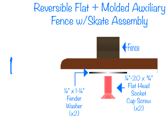
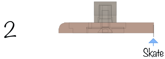
It is flat on both sides and 3/8" thick. It has a molded front to match the end-grain profile of the molded fence that we will see further below. The metal part you see is a 0.015" thick piece of tempered mild steel that will be epoxied onto the wood and will act as a skate for kerf bending or kerf-driven spacing if/when desired. There is no concern of cutting yourself on this thin strip of mild steel for two reasons. First, I filed a bevel on the edge until it was safe to the touch, and second, there is another part that connects to this piece that acts as a sheath to cover the exposed portion of the skate when not-in-use.
This flat fence is actually reversible. You can have the skate pointing up (to get it out of the way, providing a smooth flat surface to utilize against the stock you intend to cut) or you can have the skate pointing down (either to ride in a previously-cut kerf or obscured by the molded hand-fence, introduced later in this post).
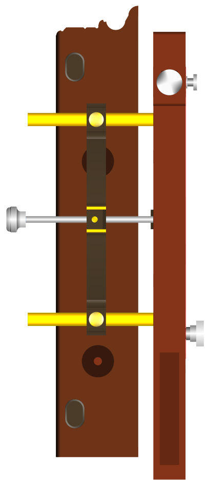
Let's connect this flat fence to the plane. First, if we connect it with the skate pointing up ...
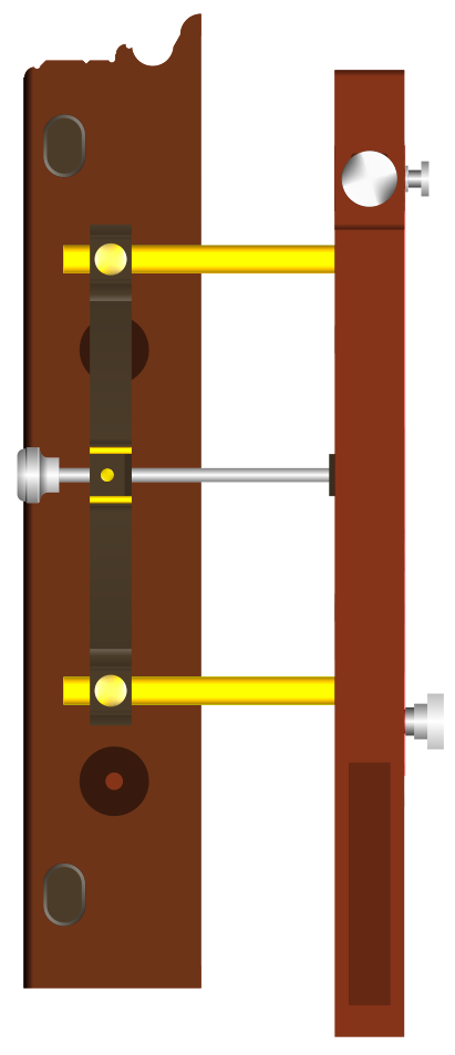
Or if we connect it with the skate pointing down (pictured below):
Let's go through that one more time, but from the overhead view. First (pictured below), with the skate pointing up:
And now the skate pointing down:
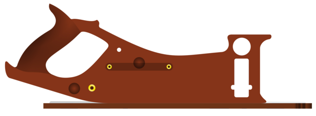
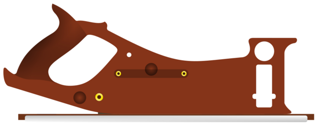
Let us now take a look at the Carcass from the side with this fence attached. First, on the right-hand side (where the saw attaches) and with the skate up:
and skate down:
If we flip 180 degrees to have a look at the left hand side of the plane with this fence attached, this (pictured below) is what we see (first, skate-up):
and skate down:
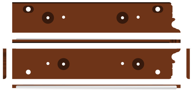
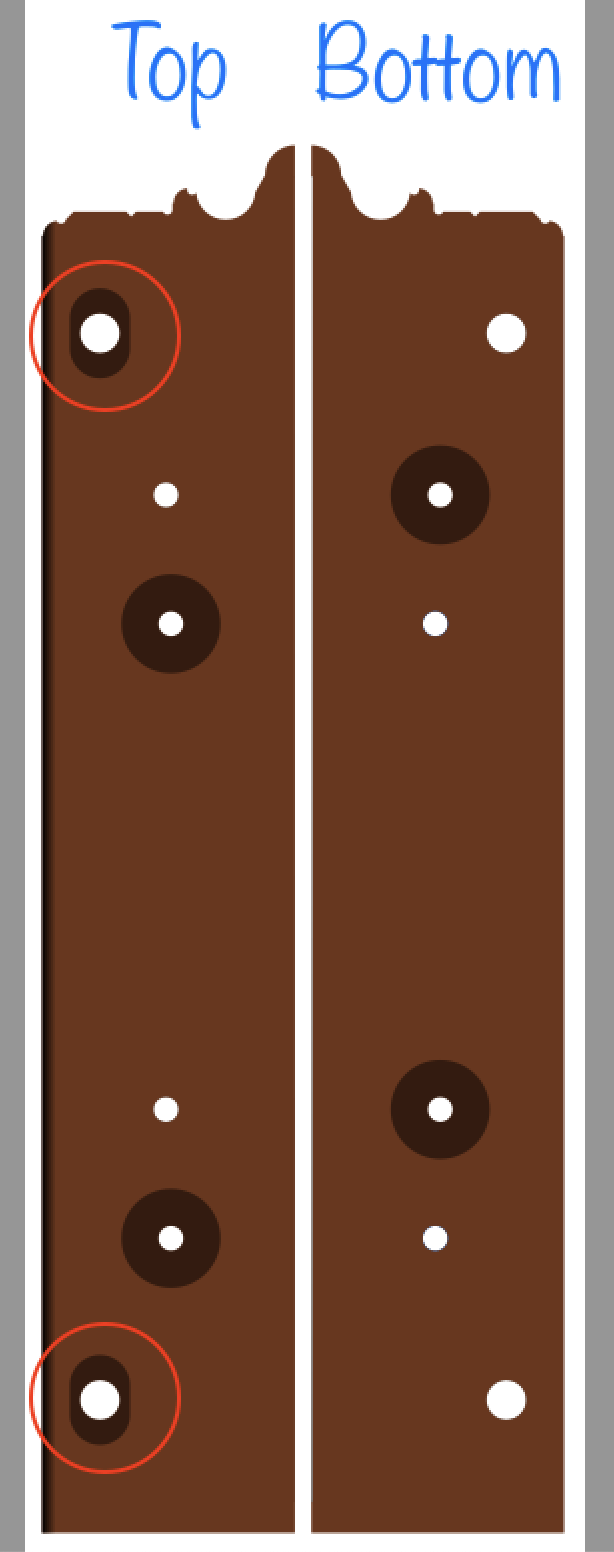
However, this flat auxiliary fence is holding a secret. It may be reversible in the sense that you can flip it over, but the two sides are not exactly the same. On the "top" side (with the skate pointing down) there is an oblong pocket stationed at either end. These pockets are for bushings that allow you to attach yet another fence to it.
That may not be discernible from the photos immediately above, so let's see. Top versus bottom side-by-side, as-from-above:
What I am referring to is the left-hand oblong pockets on the top of the flat fence. Circled in red below:
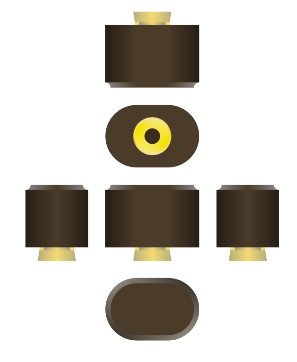
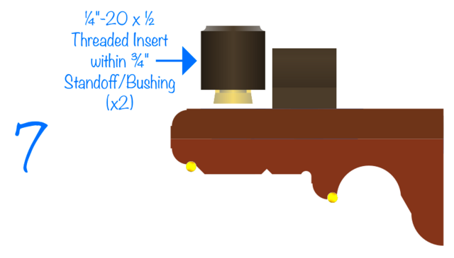
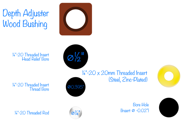
Those accommodate bushings that look like this, nothing more than a threaded insert shoved (mostly) into an oblong piece of Ebony:
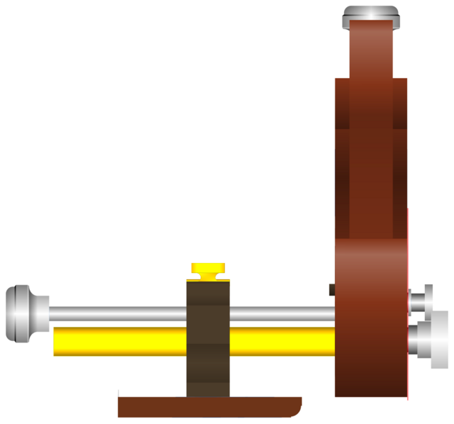
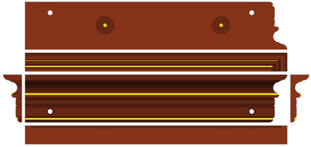
With two of those set atop the flat fence, the threaded insert extends (nearly) flush with the bottom. The purpose of which is to attach a hand fence, for your hand. All put together, it will look like below:
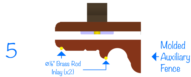
This is where I get to introduce the molded hand fence, which bolts to the underside of the flat auxiliary fence, which itself bolts to the main fence that slides over the 2 brass arms of the plane.
Let's have a look at the 6-up orientation for the molded hand fence before we see it in-assembly:
If you have trouble imagining the molded fence, picture an old wooden plow plane fence (those words are easier typed than comprehended; if that gives you trouble, picture a hunk of crown molding, with brass rod inlay).
Why the brass rod inlay? Because when you set the plane down, those are the points of contact with the bench, protecting the molding from damage and extending the life of the plane.
Now let's have a look at how this piece fits into the fence puzzle:
Step 1 involves attaching the flat fence to the main fence:
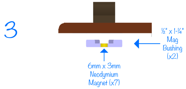
Up next we introduce something called a "mag bushing" which is really just a fancy word for a piece of acrylic with a magnet in the center. The magnet in the center of the acrylic is attracted to the 1/4-20 cap screw used to hold the flat fence to the main fence.
There are two magnets recessed into the molded fence. These help track and hold the molded fence to the flat fence while you are bolting them together (because I thought it would be really annoying and cumbersome to have to hold these things together while bolting them together; therefore once you get the flat fence bolted on, it's just a matter of slapping the mag bushings over the screws and the molded fence atop the bushings, allowing one to hold the plane by its handle while screwing the molded fence on).
The bushing sticks out the bottom and is held in place by both magnet and recess in which it sits:
Now we bring the molded fence close to the bushing, and the magnets epoxied into it do the rest.
At this point, it would be tempting to use, but it's only held together with magnets.
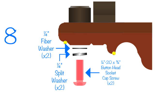
Let's bring in a pair of (Ebony) bushings with threaded inserts poking out of them. These will hold the molded fence to the flat fence.
Now, we're going to want a really strong hold here. Nobody wants the 2 fences to come loose, and so we use a split lock washer. Also, nobody wants time to cause that split lock washer to erode the pocket, so we'll slip a fiber washer between it and the wood. Double-duty, the fiber-washer has such a tight tolerance on its internal diameter, that it keeps the split lock washer on the screw so that it doesn't fall off whenever you take the screw out from the insert.
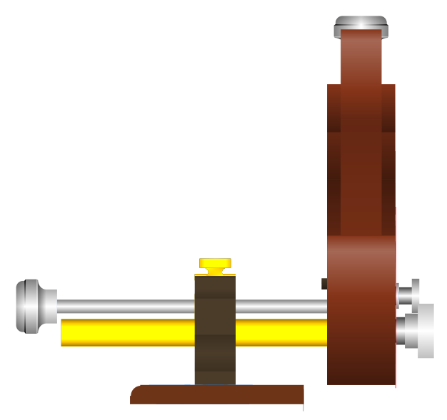
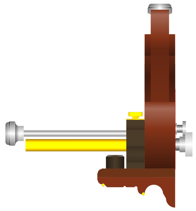
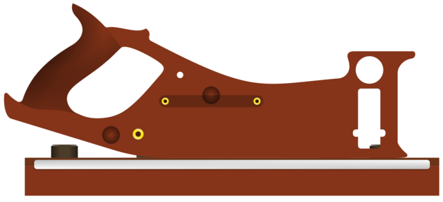
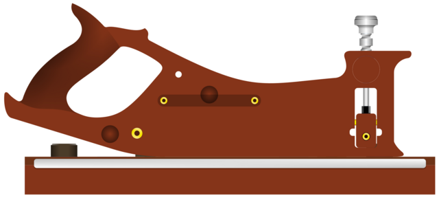
Returning with this full fence assembly, we can more readily explore what the plane will look like from various angles. Let's start with profile view:
Now overhead view:
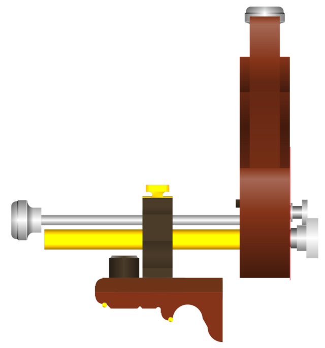
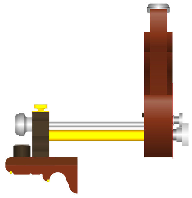
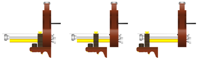
And now side views:
I have taken you through a lot, but I have not demonstrated above how a saw is supposed to attach to this thing. Let us focus on that now.
The rear end of the saw is connected via M6 shoulder screw while the front is connected via M4 shoulder screw. The M6 connection is uninteresting, it is simply the M6 shoulder screw that comes bundled with the Vaughan BS250D, blade purchased with handle. The M4 connection however is elaborate to say the least.
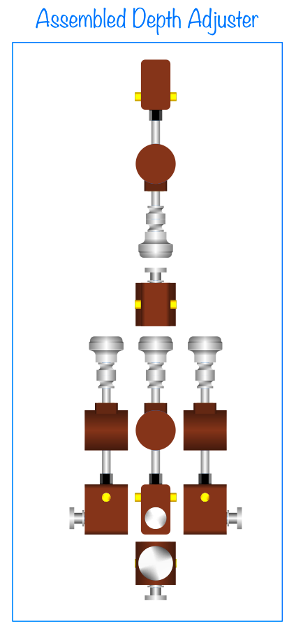
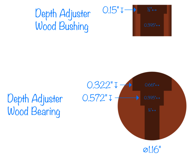
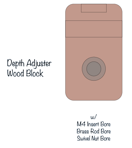
The hang-hole of the BS250D is approximately 9mm in diameter and it will connect to a depth adjuster whose 6-up orientation is pictured below:
It consists of:
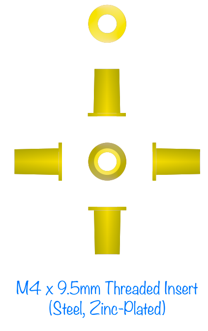
1. an M4 shoulder screw (knurled) 2. a 1/4-20 domed knurled knob 3. a 1/4-20 threaded rod 4. a 1/4" dia. brass rod (unthreaded) 5. an M4 threaded insert 6. a 1/4-20 swivel nut 7. two 1/4-20 knurled thumb nuts (opposing) 8. a 1/4-20 threaded insert 9. epoxy 10. 3 wooden pieces (a bushing, a bearing, and a block)
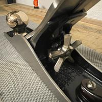
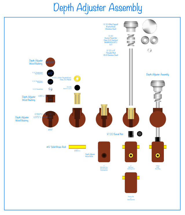
Let's take a closer look at these components:
Alright, that wasn't a very close look, you can barely read the text. That was just a view of what we are going to be focusing on below:
The bushing accommodates a threaded insert. The threaded insert is longer than the bushing. The bushing goes into a bearing. The threaded insert locks the bushing to the bearing (with epoxy also). This allows me to insert the bearing from the side of the plane and then the bushing from the top, lock the two together, and now the depth adjuster can pivot about the bearing's axis of rotation. This rotation is required because one side (the rear) of the saw is pinned by the M6 shoulder screw and, aside from the prescribed rotation, does not move. Since the saw rotates about a center as it descends, the depth adjuster needs to come closer or extend further to account for the fact that the two holes must remain equi-distant at all times (else the saw plate will buckle -- that's just a fancy way of saying that the toe hole scribes an arc as it rotates about the M6 screw hole and the depth adjuster has to move slightly as it ascends/descends).
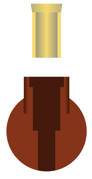
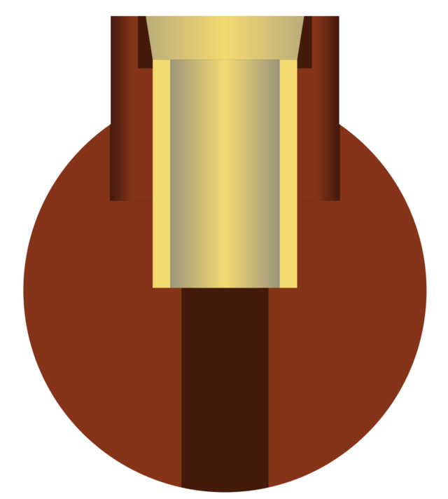
Those two units above get shoved together, as shown below, and a long threaded insert is brought in:
The threaded insert will mate the bushing and bearing together. This is not hard (if prepared for). First, the bushing is not round, it's a rounded rectangle (why rounded? so that the recess for it can have fillets and I don't have to chisel them square) meaning that I can pre-thread each unit separately and carefully so that when it comes time to run the insert with epoxy, it will simply be traversing the already-cut grooves.
ASIDE: These are small parts. Running a threaded insert into such small parts is likely going to yield broken parts. That's why in my order of operations, I cut a larger piece from which I bore the recess for the inserts, run the inserts into these larger pieces to pre-cut the grooves for the thread, then in a separate setup cut out the parts. That way I am never stressing the wood beyond what it can handle.
The next thing we bring into the depth adjuster is the threaded rod, knurled nuts, and domed knurled knob. The threaded rod passes through the threaded insert in the bearing (for simplicity sake, I will refer to the fused bushing/bearing combo simply as "the bearing" as this is its primary function -- the fact that there is a bushing to pin it into the assembly is really not important).
The threaded-rod in the picture above is truncated.
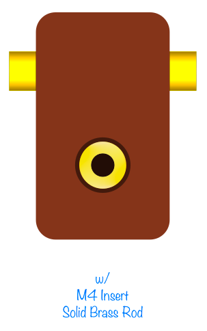
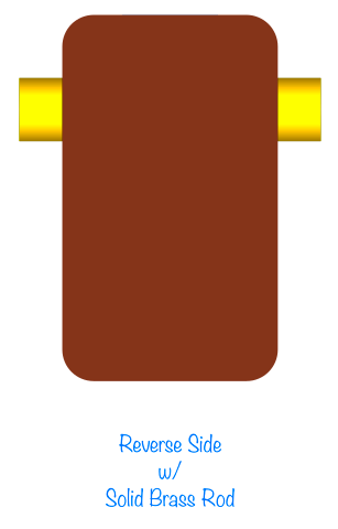
Below the bearing in the depth adjuster assembly is the block which contains the M4 threaded insert by which the M4 shoulder screw will pin the hang-hole of the saw plate to the plane.
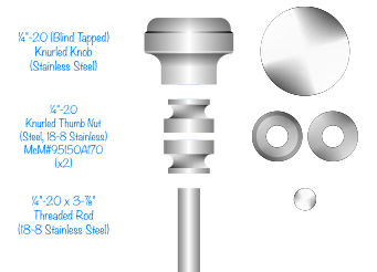
Below is the hardware that we bring to this block at the end of the depth adjuster:
And of course an M4 threaded insert (pictured below):
You bring these three components together with the 1/4-20 threaded rod and you have yourself a depth adjuster.
In outline view (aka X-ray mode):
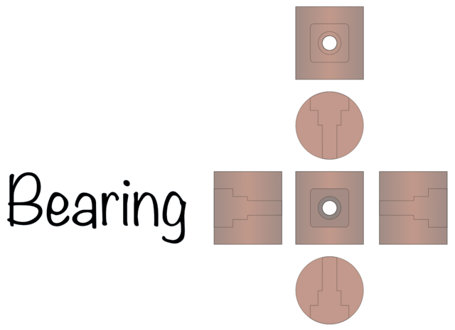
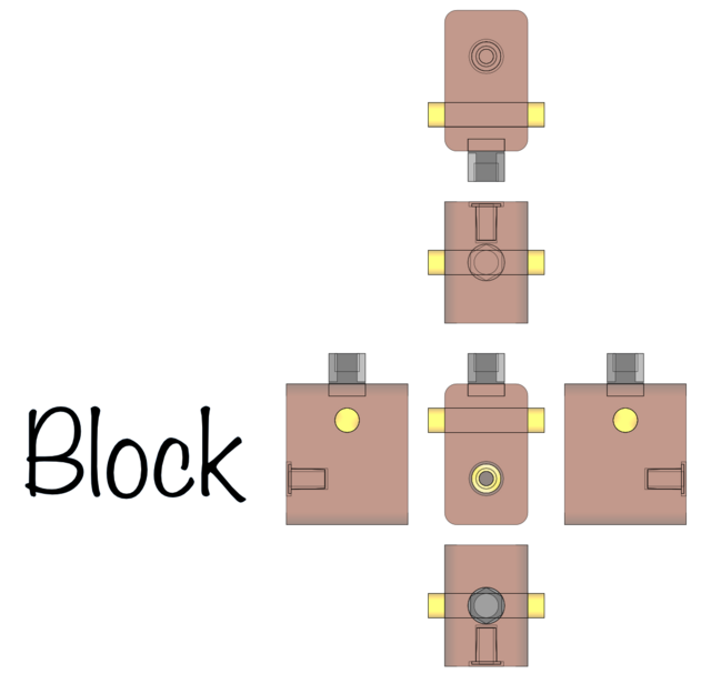
Because the depth adjuster is a rather critical part of the design, let's see some 6-up orientations on the separate components that go into its design (we already saw a 6-up orientation for the wholly assembled depth adjuster, but seeing the three components separately is helpful):
Now the bearing:
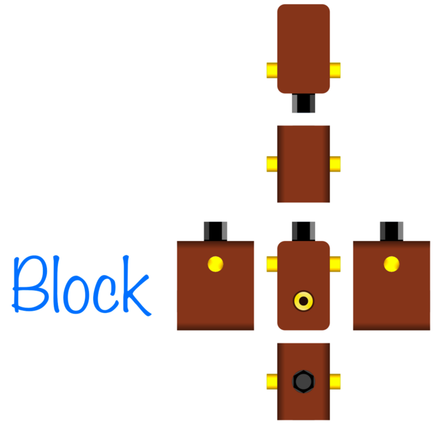
And finally the block:
Wow, OK, now we can return to the side-views to incorporate the depth adjuster assembly.
HINT: The overhead and profile views previously shared already had the depth adjuster on them, however I thought including them in the side views was muddying the waters, and so wanted to picture those initially without the depth adjuster for clarity.
Now, before we go attaching the saw plate, let me reveal the purpose of one of the fixture recesses on said side (because the item that goes into that feature sits behind the saw plate).
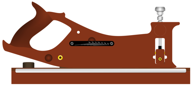
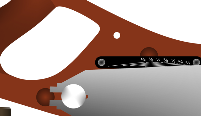
There is a fixed depth gauge. It is made of black plastic. I made it for this design specifically. It goes here:
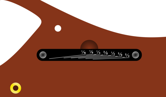
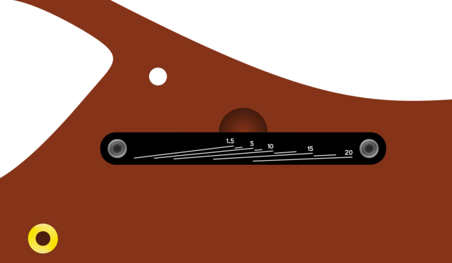
I made one for Imperial (in fractions of an inch) and one for Metric (in millimeters).
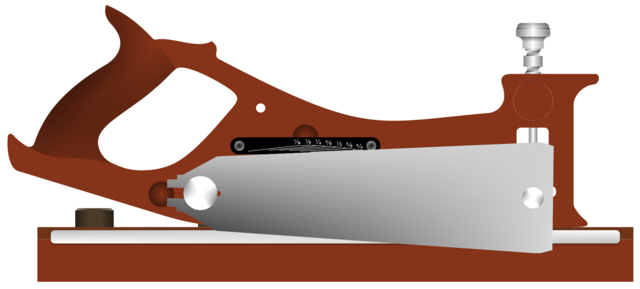
Alright, so let's slap the blade on there:
What's that depth gauge say? Looks like it reads just-over 3/4"
As you adjust the depth, the top of the saw plate tells you the depth of the bottom of the saw plate relevant to the sole of the plane.
ASIDE: Yes, I am aware that this means that if you resurface the sole of the plane that the depth gauge will be slightly off. That's why the depth gauge is replaceable.
We're not done yet. You see that little hole above the depth gauge?
With the exception of the M4/M6 threads holding the saw plate and depth gauge onto the plane, every other thread is 1/4-20. All such 1/4-20 screws are Allen head and so I've devised a way to conveniently hold the Allen key on the tool. You shove the long end of an L-shaped Allen key into the hole from the fence side of the plane and a magnet grabs it and holds the short end of the L-shape in a recessed slot.
I analyzed lots and lots and lots of L-shaped Allen keys and created a slot that will hold them all, short and tall. Let's take another look at the profile, overhead, and side views with the Allen key tucked into the plane.
Can you see it poking through the hole? Let's rotate to the other side.
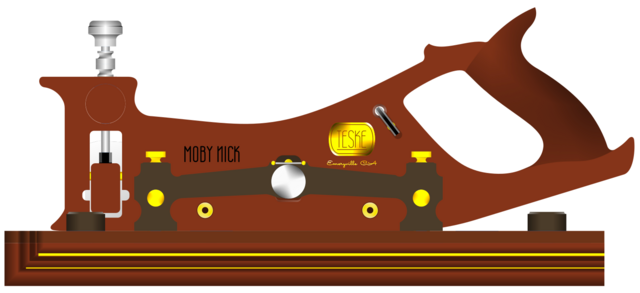
Can you see it there? Oh, and look at that, we grew some engravings. The "Teske Tool Co" company brand in Gold, the origin of birth (also in Gold) beneath that, and the model name -- Moby Nick.
Oh, and if you are looking closely, there's also something else I haven't shown before, and that's a ruler. Look in-between "Moby Nick" and the "Teske" logo, just above the main fence, there is a metallic bar -- that's a Starrett Ruler.
Here, you can see it better from the overhead:
Above we can see how far the Allen key, nestled in its slot from the fence-side, sticks out the saw-side. The Allen key is fully recessed in its slot with no thumb divot to pull it out -- to get it out, you push from the saw-side to release it from the slotted/recessed magnet. The slot is rotated away from perpendicular with the sole so that once you do push it enough to get it out of the slot, gravity will naturally cause it to drop to perpendicular (preventing the magnet from pulling it back into the slot). That way when you take your hand off the Allen key you can simply grab the short end without trouble (unless you have the plane tilted to the left in which case the key will drop to the floor).
ASIDE: I for one look forward to having contests to see how far one can launch the Allen key across the room with a single finger. That way when a fellow shop buddy is not looking, I can have a little fun.
all of it -- well, except for ... (mumble mumble).
Can I per-chance make it any clearer? Yes, I think I can. By taking some dynamite and placing it in the center of the thing.
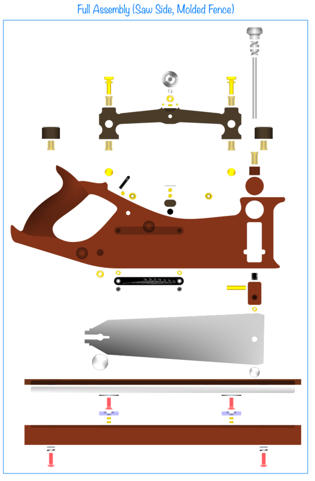
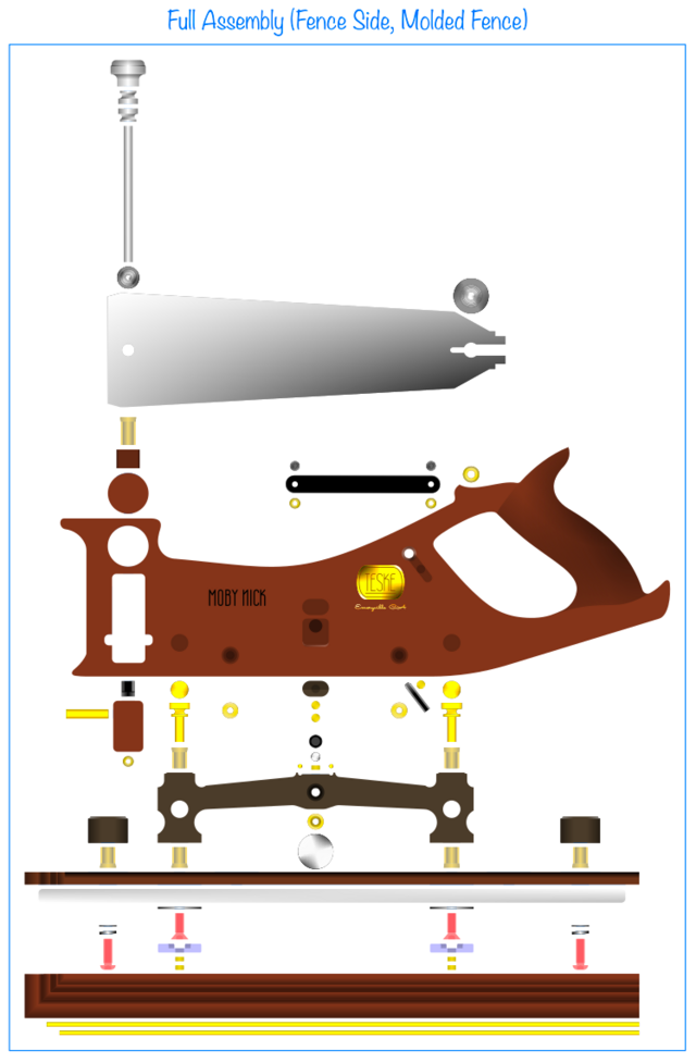
If we explode the thing:
I did not cover 3 things -- one of which I will never cover publicly (how I sign my work and the slight imperfections that I introduce to help me identify fakes).
The other things I did not cover, I will cover now.
The brass rod in the depth adjuster block gets pinned in the center of the body of the plane in a channel that is cut with a keyhole router bit. That is to say that there is a 1/4" diameter slot mid-way through the thickness of the 1-1/4" thick carcass that ensures that as the saw plate experiences forces attempting to pull the saw plate away from the body, that brass rod in the adjuster block prevents any lateral movement. The slots for this brass rod are wide enough to accommodate the rotation that the depth adjuster will exhibit as the bearing rotates.
The last thing to cover that was not covered was ...
(cuts it "short" ... being summoned to help with the child ... too-da-loo)
well based on how long youve been at this with the time constraints and lack of shop space, plus what your showing us, i think once this thing is complete and comes to fruition as shown, i dont think there will be any doubters as to your vision ? im getting excited !
working with my hands is a joy,it gives me a sense of fulfillment,somthing so many seek and so few find.-SAM MALOOF.
I am very excited and eager to share the finished products of my hard work.
EDIT: I already have a good mental picture of what the stand for this thing is going to look like. A few hardwood dowels, a couple catch-all pockets, a recess to hold the two Allen keys (shadow-foam style, but in wood), and a couple arms to hold the brass rods as well as a seat for the handle; all atop a hardwood base with molded profile. Also a place for engraving the name of the recipient for personalization and serial number.
Thank you, Eric. I have had the encouragement of a few good Craftisians propelling me forward. Plus, I would be lying if I said the entire goal was to cut wood. Part of the fun for me is creating a new tool. If I had simply cut the wood (for the boxes and shelves I need to make) then I would not have created my own tool. Much of the satisfaction comes from creating a tool that is not a carbon copy off a Pinterest or something inspired by Instagram, nor some odd-ball AI creation — but something crafted by me for me, my friends, and my progeny.
Devin, you've definitely put a lot of work into this project. That is an amazing amount of detail you provided and I like how the design improves as it progresses. Following along and looking forward to the results.
i think up till now many thought this was a unicorn ! ive been with dev since day one when we first met and never doubted her vision for this tool ! she has never not amazed me with her abilities with the limited amount of tools and machines she has to deal with. i truly believe this tool will blow you away !
working with my hands is a joy,it gives me a sense of fulfillment,somthing so many seek and so few find.-SAM MALOOF.
You lost me at "Have I lost you yet", but that is not your fault.
It would have helped if you threw in a "behold!" here and there.
I looked at all the pictures and this is very interesting. I little concerned that you are giving to much intellectual property away, and Woodpeckers will have a one-time tool version in a month.
Looking forward to the finished product, and how-to videos.
Petey, I think it is my fault to have lost you at that point as, milling it over, all throughout this blog I never once turned on any of the numerous “Notes” layers that have clear unambiguous text and arrows pointing at individual items. I will edit the post and slip that in right at that point where I think it is needed based on your helpful feedback. I am kicking myself for not inserting that “slide” which would be extremely helpful at that point.
As for Woodpeckers or others with more resources than myself churning out a small batch to test the market for such a product. I would be against such a thing because in my experience the execution could be done poorly and taint the market for the tool. There is a simple solution for situations like this, and it is called a utility patent. Copyrights are implicit these days, you don’t have to apply for one, however a utility patent prevents competitors from making a similar product for a certain number of years so that your company can get the product off the ground. I have been contemplating such a patent and the reason my drawings are so detailed is because I want to avoid hiring an artist which is often the most expensive part of filing the patent. Once it has been received you will get a pending number and this can be applied with “Pat. Pend.” to the finished tool as well (CNC engraving, etc).
I haven’t yet priced out the cost of filing such a patent, but multiple people have told me that I should, and I tend to agree. What do others think?
I am hording my “behold!”’s — don’t want to use them all up in one time 😉
When my sister and I were about 10-11 years old, we were hanging out with Dad and we were walking through a store and discovered Koosh balls. The whole family got them; they were super fun.
Sister came up with the idea to make Dinosaur Koosh balls. She is an amazing artist and drew up hyper-realistic Koosh balls that had dinosaurs inside them.
This doesn’t sound so crazy today because there are Koosh animals. All sorts of animals, fish, even an Alligator was made by the company. However to this day, as far as I am aware of, there has never been a Dinosaur Koosh and you can thank my sister for that. Dad encouraged her to send her drawings to the company and they sent them back with a letter stating they would never make such a product. Roughly about 5 years later, Koosh Animals came out.
Nothing can protect an idea forever. My sister was only 11 or 12 at the time if memory serves. We didn’t know anything about copyrights, utility patents, or whatever. Her and I just wanted Dino Koosh balls and could not ever conceive of a way to make them ourselves, so we made a suggestion. That suggestion back-fired and here we are today with all manner of things shoved into the center of a Koosh creation, but nothing of the prehistoric sort to share with OUR children.
The lesson I learned there is, don’t make suggestions, just do it. If you want it, go get it.
If my kid wanted a Dinosaur Koosh today, I’d start looking into injection molding and do it myself. Personally, the letter they sent back made me so mad I never bought another one of their products again.
Petey, you were right. I re-read that section and there was even more missing content than I realized earlier.
I have added the missing bits. I went back and re-read the whole article and I didn't talk enough about the bushings used to connect the two auxiliary fences together. That has been corrected.
I also did not talk about (but see no reason to add unless there is demand) how the ruler (be it Starrett or Mitutoyo) magnetically attaches to the fence/body to act as a gauge for the fence. It's rather uninteresting and can probably be discerned from the photos already provided, but if anyone is interested, I can describe it.
I have a neighbor with many times more money than I whom is always in his garage playing with his toys.
He says he wants a lot of things. I think to myself, “you have the money and the time, just buy the damn CNC plasma cutter you keep talking about.”
But he doesn’t buy it. I don’t get it. He is constantly asking me to cut things for him. Last I cut a piece of his roof rack on his zombie apocalypse vehicle, so he could mount some other accessory.
I just think people are lacking focus today. Like they may have the energy, the means, and the spirit, but they for whatever reason don’t do what they talk about.
Not doing something you talked about is anathema to me. I am ever fearful that I become like my neighbor or those like him. If I talk about something, I do it, live it, breathe it, etc.
My word is not my bond, rather my words are me, and I am my words. Speak then do.
To be accused of lacking follow-through would in my mind be the highest accusation that could be lobbied.
Everything I have talked about will be done. Years ago, I talked about:
1. Engine turning hand planes for fun and profit, testing a principle stated in a 1970’s benchwork book that engine turning makes iron rust proof
2. Inventing a new novel hand plane depth adjuster from a little known tractor part to alleviate myself from supply chain issues from Lee Valley experienced during the pandemic
Few have ever realized that by the time I start talking about something, wheels have been set in-motion that all but guarantee production.
Too many times have I been burned by people that talk but do not walk, and I make it a serious mission statement to myself that I will never be that person — that even if it takes me decades, I will do what I say and say what I do
I remember when I was younger, and I would chase down my dreams, and eat them up. If I said I plan to: then I did it in pretty quick order. Used to say I'll sleep when I'm dead a lot too.
It's funny, at 69 I am doing a lot of that sleeping now. I think maybe you burn up your allotted "action minutes" then when you actually have the time to "tinker in the shop" all you want to do is take a nap. Seems it's how it's working out for me anyhow. :-))))
That’s why, in my 40’s, I am pushing myself harder than ever.
A few things might not be working as optimally as they have in the past, but I recognize the finite resource and as such am using my physical endurance while I have it.
Much of endurance today is actually tricking myself into thinking that what I am feeling is not pain. Remember back when you were young, and questioned whether something was pain or just a funny feeling. I just ask myself one thing: if I continue will it get worse or better? Often times it’s better or unknown, in which case the answer is forge-on, what pain? That’s not pain, it’s experience. Push through. Anything worth doing is not easy. Perceived value is lavished upon only those that make it over the finish line. And many other things I tell myself whilst running actual marathons.